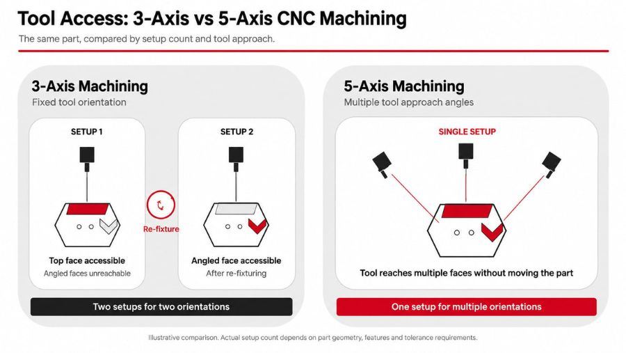
Choose 3-axis CNC machining when the part’s critical features are accessible from one or a small number of fixed tool orientations and the additional setup, programming, and machine cost of 5-axis machining would not provide a practical benefit. Choose indexed 3+2 or simultaneous 5-axis machining when multiple faces, angled features, or deep cavities cannot be machined efficiently with practical 3-axis tooling. These approaches are also valuable when the tool orientation must change continuously while maintaining controlled positional relationships. Simultaneous 5-axis machining is most valuable when the tool axis must change continuously along a complex or freeform surface.
Why the Right Process Choice Matters
The choice affects setup count, achievable tolerances, programming time, and total cost. Picking the wrong one can mean rework, missed tolerances, or paying for capability a part doesn't need. This guide walks through the 3 axis vs 5 axis decision by geometry, setup requirements, accuracy, and cost, and explains when indexed 3+2 machining is enough versus when simultaneous 5-axis motion provides a meaningful advantage. For a broader look at how CNC machining works before comparing these two approaches, see What Is CNC Machining.
3-Axis vs 5-Axis at a Glance
| Factor |
3-Axis Machining |
5-Axis Machining |
| Tool access |
Reaches the part from a fixed tool orientation; angled, recessed, or partially undercut features may require re-fixturing, specialized tooling, or another approach |
Tool can approach from multiple angles and may provide access to many angled, recessed, and partially undercut features. Feasibility still depends on tool and holder geometry, machine kinematics, clearance, and the exact feature geometry |
| Setups for multi-face parts |
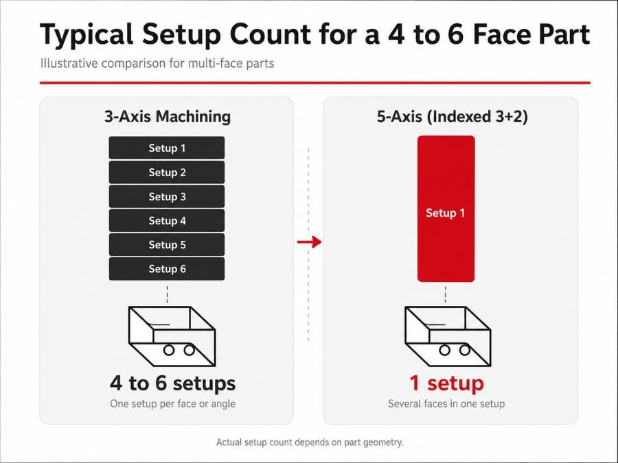
May require multiple setups when different faces or tool orientations cannot be reached from a single setup |
Often one setup for several faces, especially with indexed 3+2, but additional setups may still be required for blocked or underside features |
| Datum transfer |
Each re-fixturing re-establishes a datum, adding stack-up risk between setups |
Fewer re-fixturings can reduce datum-transfer risk for features that must stay in tight positional relationship, but do not eliminate machine, tooling, fixture, thermal, or kinematic error sources |
| Positional consistency |
Strong for features cut in a single setup; weaker across multiple setups |
Can improve consistency across related features on several faces when re-fixturing is reduced, but the result still depends on calibration, probing, fixturing, tooling, and process control |
| Surface finish on contoured geometry |
Can achieve high-quality finishes with suitable tooling and toolpaths, although complex freeform geometry may require more stepped paths or smaller stepovers |
Simultaneous 5-axis machining can improve finish on certain freeform surfaces by maintaining a more suitable tool orientation and reducing the need for heavily stepped toolpaths; it does not automatically guarantee a better finish |
| Fixturing |
Simpler fixtures; may require multiple fixture setups per part |
Often requires more open-access fixturing and greater clearance around the part; fewer setups may be possible, but the fixture can still block some geometry |
| Programming complexity |
Straightforward toolpaths, shorter programming time |
Longer programming and verification time, particularly for simultaneous toolpaths, with greater reliance on machine-specific simulation and a validated post-processor |
| Typical cost driver |
Lower machine and hourly rates; cost rises with number of setups |
Higher machine and hourly rates; total cost may decrease on complex parts when setups and handling are consolidated, but can remain higher for simple parts or low volumes because of programming, simulation, inspection, and machine time |
| Best-fit part examples |
Plates, brackets, simple housings, features on one or two faces |
Multi-face housings, manifolds, turbine- and impeller-style components, parts with angled or contoured features |
Choose 3-axis machining when
- Part geometry is mostly flat, prismatic, or reachable from one or two faces
- Tolerances are tight but concentrated on features cut in a single setup
- Production volume and cost favor simpler tooling and faster programming
- The geometry does not require continuous changes in tool orientation along a freeform surface
Choose 5-axis machining when
- Features are spread across multiple faces or angles that would otherwise need several setups
- Positional relationships between features on different faces must hold tight tolerances
- The part includes deep pockets, angled holes, recessed features, or partially undercut geometry where tilting the tool or workpiece can improve access or allow the use of shorter, more rigid tooling
- The surface geometry benefits from continuous changes in tool orientation, such as blades, impellers, or organic contours
A quick decision sequence
- Can the part be finished from one or two fixed tool orientations using practical tooling and without problematic hidden geometry? If yes, 3-axis machining is usually sufficient.
- Does it need several faces machined with tight positional relationships to each other? Indexed 3+2 machining is often enough.
- Does the surface require the tool axis to change continuously along the cutting path, as with certain blades, impellers, or complex freeform surfaces? Simultaneous 5-axis machining may provide the most practical approach.
Indexed 3+2 vs. Simultaneous 5-Axis Machining
Not all 5-axis work involves continuous motion. There are two distinct forms of 5-axis machining, and they suit different part geometries.
What Is 3+2 (Positional) 5-Axis Machining?
In indexed 3+2 machining, the rotary axes position the workpiece or spindle at a programmed orientation. The cutting operation then proceeds with the rotary axes stationary, using a fixed tool orientation for that operation. The rotary axes do not necessarily have to be mechanically locked; the exact implementation depends on the machine and control. 3+2 machining suits prismatic parts such as housings, manifolds, and brackets, where the goal is reaching multiple faces accurately in one setup rather than continuously changing the tool orientation along a curved surface. It is often simpler to program and verify than simultaneous 5-axis machining and can be a very stable approach for suitable geometry.
What Is Simultaneous 5-Axis Machining?
Simultaneous 5-axis machining is a process in which the linear and rotary axes move together during the cut so the tool orientation can change continuously along the path. It is especially valuable for complex freeform surfaces, turbine-style components, impellers, and other geometry where a fixed tool orientation would be inefficient or would compromise access, tool engagement, or surface quality. Some parts that appear to require simultaneous 5-axis machining can still be produced using indexed 3+2, specialized tools, swarf strategies, EDM, or a combination of processes, depending on geometry and tolerance requirements.
A Note on Accuracy: Neither Process Wins Every Time
More axes doesn't automatically mean more accurate. For a geometrically simple part machined entirely in one 3-axis setup, with short, rigid tooling and stable datums, 3-axis machining can be just as repeatable as a comparable 5-axis job. Added axes bring their own kinematic and programming variables, including rotary-axis accuracy, machine calibration, tool-center-point compensation, post-processor behavior, and the possibility of unfavorable machine orientations.
5-axis machining can gain an accuracy advantage where it reduces re-fixturing between related features or improves tool access while maintaining shorter, more rigid tooling. Which process is more accurate for a given part depends on geometry, GD&T requirements, machine condition, tooling, fixturing, thermal stability, calibration, and process control, not a fixed rule that one process is always better.
Surface Finish: What 5-Axis Can and Cannot Improve
Simultaneous 5-axis machining can improve surface finish on certain freeform surfaces by maintaining a more suitable tool orientation and reducing the need for heavily stepped toolpaths. However, surface finish is influenced by tool geometry, tool diameter, stepover and scallop height, cutting speed, feed rate, machine and workpiece rigidity, vibration, tool deflection, CAM calculation quality, post-processing, and controller behavior. A well-planned 3-axis process using appropriate tooling, such as a ball-nose cutter with a suitable stepover, can also produce an excellent finish. The number of axes alone does not determine surface quality.
Undercuts and Hidden Features
5-axis machining can provide access to many angled, recessed, and partially undercut features, but it does not make every undercut machinable with a conventional end mill. Feasibility depends on the exact geometry, machine tilt range, tool diameter, holder clearance, fixture clearance, and collision risk. A true geometric undercut may still require a lollipop cutter, T-slot cutter, angle tool, custom tool, EDM, a separate operation, or a design change.
Machine Configuration, Fixturing, and CAM Considerations
“5-axis machining” does not describe a single machine configuration. Table-table, head-table, head-head, trunnion-style, and mill-turn architectures differ in rotary travel, stiffness, working envelope, clearance, and access to the part. These factors can affect whether a feature is practical to machine and how accurately it can be produced near the limits of machine travel.
Fixturing for 5-axis work also requires enough clearance for both the tool and the moving machine components. Open-access workholding, soft jaws, dovetail fixtures, trunnions, tombstones, or other dedicated fixtures may be used depending on the part. Even with 5-axis capability, the fixture can block the underside or other regions, so a second setup may still be necessary.
For simultaneous 5-axis work, machine-specific CAM simulation and a validated post-processor are important parts of process planning. Programming and verification should account for tool, holder, fixture, and machine collisions, rotary-axis limits, abrupt orientation changes, singularities, rotary-axis speed, and controller behavior.
Where 5-Axis Adds No Meaningful Value
5-axis capability doesn't help every part. Simple, low-face-count geometries with no tight cross-face tolerances or geometry that benefits from tool-axis changes are usually machined faster and more economically on a 3-axis machine. The added programming, simulation, fixturing, inspection, and machine cost of 5-axis machining may not translate into a better part.
Choosing the Right Process for Your Part
The most reliable way to decide is to review the drawing against the factors above, face count, positional tolerances between features, surface type, tool access, workholding, and the required GD&T and datum configuration, rather than defaulting to whichever process sounds more advanced. Both approaches fall under ShvaveyMetal's precision CNC machining capabilities.
Reviewing a part that might need indexed 3+2 or simultaneous 5-axis machining? ShvaveyMetal's 5-axis CNC milling services team can assess the drawing, feature geometry, tool access, and tolerance stack-up as part of the quotation process to recommend the right approach.